DSharp Studio is a Windows application. When starting the application, you’ll need to activate a license. If there are multiple licenses available to you, please select the one that fits your purpose.
The Modes
DSharp Studio has two Modes:
- Design Mode: build the model using the design tools available
- Run Mode: operate on the converted end result, the DW solution
After creating or opening a project, you will be in Design Mode, where you will work with your model and mappings. Once you are ready to run the model, you press the Play button to do so. At this point, your model will be validated, and if there are no critical errors, DSharp Studio will proceed to convert the model into a DW solution. Once that has happened, you enter Run Mode, where you can operate on the converted end result. In this mode, all design features will be disabled. To make further changes to your design, re-enter Design Mode by pressing the Stop button.
Design Mode

Run Mode

Understanding the Selection
All commands operate on the current UI selection made in the active pane. Some commands work with only one element selected, others may need two or more elements selected. Some commands are adaptive, meaning they behave slightly differently depending on how many elements have been selected. Some commands disregard the selection entirely.
There are three aspects of the Selection to understand in order to take full advantage of the commands:
- Selected elements: a set containing every element that the user has individually selected in the UI. The number of Selected elements can be anything from zero upwards. If it is zero, there is no selection.
- Selected element: if the number of Selected elements is 1, that element will be the Selected element. If the number of Selected elements is anything else than 1, Selected element is nothing.
- Extended selection: A set of elements that contains every element in Selected elements, but also every descendant element that is a Class or a container (Model or Submodel) for each container in Selected elements. This applies to the Conceptual model branch in the Models tree. So just click on Conceptual model, and every Class in your model is contained in the Extended selection. Unleash commands!
Some Selection Examples

- Selected elements contains the class Employee
- Selected element is the class Employee
- Extended selection contains the class Employee

- Selected elements contains the submodel Employee
- Selected element is the submodel Employee
- Extended selection contains the submodel Employee and class Employee

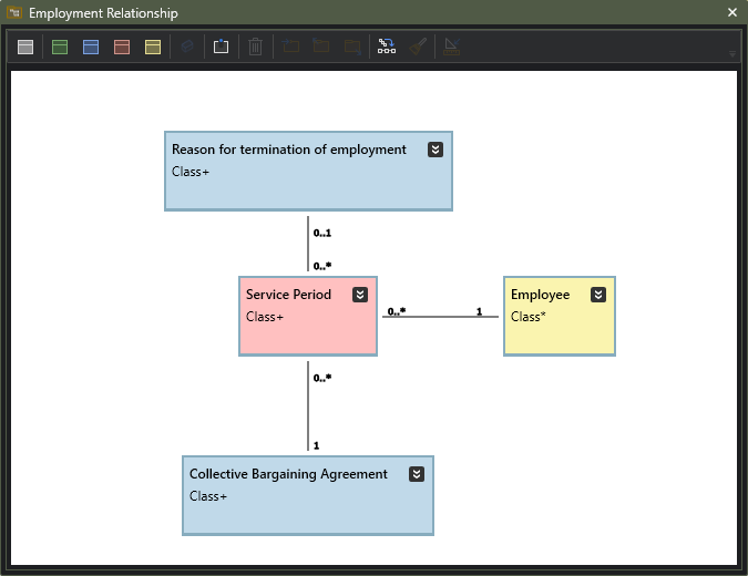
- Selected elements contains the classes Employee and Collective Bargaining Agreement
- Selected element is nothing
- Extended selection contains the classes Employee and Collective Bargaining Agreement

- Selected elements contains the class Employee and submodel Service Period
- Selected element is nothing
- Extended selection contains the classes Employee, Collective Bargaining Agreement, Reason for termination of employment and Service Period as well as the submodel Service Period

- Selected elements contains the submodels Finance, Sales and Service Period as well as the classes Employee and Collective Bargaining Agreement
- Selected element is nothing
- Extended selection contains the classes Employee, Collective Bargaining Agreement, Reason for termination of employment and Service Period, as well as the submodel Service Period. It also contains all the classes and submodels that exist in the Finance and Sales submodels.
Note that if Collective Bargaining Agreement were not selected, the Extended selection would still remain the same, while Collective Bargaining Agreement would be missing from Selected elements.

- Selected elements contains the model Conceptual model
- Selected element is Conceptual model
- Extended selection contains the Conceptual model as well as its every submodel and every class in the model. Everything.
Each command operates on one and only one of these Selection aspects, and you can check it for each command in the command reference.
Some adaptive commands that work with a single element in the selection will usually repeat the same operation individually for all elements in the selection. Copy will put each element onto the object clipboard, and Set Archetype to Description will do the same thing for all classes in the extended selection.
Some adaptive commands that even in their simplest case need two elements to work (like those creating an association between existing classes) will usually also work with more than two selected elements. When applying such a command on a multiple selection, the first element selected is always the common element of what is usually a sequence of pairwise operations. For example, selecting 5 classes and running a command that creates a one-to-many association will create 4 new associations between selected element number 1 and 2, 1 and 3, 1 and 4 and finally 1 and 5, respectively.
In case of adaptive commands, the name of the command always reacts to the selection and will let you know which element is the target element, making it clear what is about to happen.
Feel free to experiment by making different selections and then observe how the command changes its name to reflect the selection and the action it is going to perform.
Design Mode
Once you have a project going, the default application layout looks like above.
- On the left side, the Models pane displays the Conceptual model and its submodels. Also, any generated models will appear here in Run Mode.
- On the right side, the Properties pane is used for modifying the selected element’s details (whether it’s a model, submodel, class, attribute, association, data connection or any other type of element). Actual editability of a specific property depends on the type of property and the state of the application.
- In the center is the main working area where more user action oriented content like the Model Editor will be shown.
- At the bottom, log, analysis results and other informational content appears.
While this layout is a tried-and-tested layout that works well for the intended purpose and natural workflow of this application, users can move the panes as they desire, even outside the application’s defined area. With a multiple monitor setup, it might, for example, in some cases be beneficial to pull some diagrams out of the application’s main window to a secondary monitor for quick reference while working on a submodel in the working area.
Generally, it can be stated that:
- The structure of the model is maintained in the Models pane (contents can also be referred to as hierarchy or tree view).
- The content of the model is maintained in the Model Editor. Note that almost all actions can also be performed in the Models pane, but since the tree view show all levels of submodels, while the Model editor only displays one at a time, some actions can be done in the Models pane that cannot be done in the Model Editor.
- The properties of model elements are viewed and edited in the Property pane.
- In addition to these, the menus and toolbars contain a myriad of usability-enhancing and time saving functions. The application also supports special input mechanisms such as Quick Input.
Models And Submodels
In the context of DSharp Studio Modeler 5.0, models and submodels are fundamental organizational units used to structure and manage the content of the model. Here’s an overview of how models and submodels function within the application.
Models
- A model in DSharp Studio Modeler represents a comprehensive conceptual framework designed to capture various aspects of a system, process, or domain. The Conceptual model is the model that is being built when you use the application.
- There is some specific need that drives the design of the model. That need defines what is and what is not important, ie what should and should not exist in the model, and what the appropriate granularity and overall detail level is.
- The model states what is true at any given moment.
- Technically and visually, the model serves as a container, organizing related elements that collectively define the structure and behavior of the modeled domain.
Submodels
- Submodels are hierarchical subdivisions within a larger model, enabling finer-grained organization and specialization of the model content.
- They allow for the segmentation of complex models into manageable sections, facilitating clearer representation and focused analysis of specific domains or subsystems.
- Submodels may encapsulate distinct functional areas, subsystems, or layers within the overall model architecture.
The relationship between models and submodels is analogous to the relationship between a whole and its parts. Models provide overarching context and structure, while submodels offer detailed perspectives and specialized representations within that context.
By leveraging submodels effectively, users can streamline the modeling process, enhance model clarity and comprehensibility, and accommodate diverse modeling requirements across various domains and contexts.
Power User tip: Build small submodels. There is no shame in even having just one class in a submodel. That usually signifies that it is a shared class that several other classes refer to, but it does not “belong” to any one of those more than the others.
Power User tip: Use the Organize commands to keep the model structure tidy.
Sandboxes
Sandboxes are isolated models that you can use exactly the same way as the Conceptual model. The only difference is that elements within a Sandbox have no implementation details, and they can’t reference anything outside their Sandbox, nor can any other element reference them from outside the Sandbox. Sandboxes can be used in situations where you, for example, want to showcase some specific software functionality or sketch alternative model structures without the risk of breaking the implementation model.
Sandbox models can also be generated from Business Cases.
Working With Projects
After launching DSharp Studio Modeler, you can start working by:
- Creating a new project
- Opening an existing project
- Importing a project from a third party tool
Importing a third party tool project creates a new unsaved project. If you are using the full DSharp Studio, you can directly generate the DW from the imported model, provided that you also have the necessary mapping files.
You can only have one project open in DSharp Studio at a time. However, you can run multiple instances of it, should you need to work on several projects simultaneously.
Power User tip: if you are regularly working with one particular project, you can tick the Open last project on startup option in Application Settings.
The Model Editor
This is the heart of the application where you visually build the model.
You should not think of it as a generic diagram editor, but rather a highly focused tool. The Model Editor keeps the diagram clean by removing classes that do not belong there. Classes that do belong there are:
- classes that are direct children to the submodel
- classes that these classes depend on, ie there is an association to the class outside the submodel that defines a dependency. For example, a Project Task is dependent on its Project, and in case Project Task class were to reside in a different submodel than Project, the Model editor for Project Task would also display Project. Classes not native to the submodel are shown as semi-transparent in the Model Editor.
Power User tip: Always create new classes with one or more to-be-associated classes selected, or press p, d, m or r while drawing the association and dropping the end onto an empty spot on the canvas.
Models
This is where you build and maintain the structure of your model. Here you can create new elements, delete unnecessary ones, rearrange, copy, paste and drag and drop. The model you are constructing is the Conceptual model, so all elements you can create and delete reside in that branch of the tree.
Models that are generated will also show up in this tree.
In the pane’s toolbar you will find the most relevant commands that allow you to quickly work on the structure right here in the tree.
Power User tip: Learn the menu command keyboard shortcuts! Start with ALT + M/P/D/R/A for class and attribute creation and CTRL+ALT+H/Q for associations. Those will get you a long way quickly.
Power User tip: Use Quick Input for creating attributes (also in Model Editor).
Power User tip: You can define the business keys for several classes in one action. Just select the key elements for each class and press CTRL+K.
Class Analysis

The Class Analysis pane shows the analysis result for the selected class. The analysis is performed in real time, and the results shown are either Suggestions, Warnings or Critical errors.
- A Critical error means that the analyzed class is not qualified for conversion before the issue is resolved
- Warnings are usually errors in classes not set to be implemented, and they will turn Critical once the class is set to be implemented
- Suggestions catch possible modeling inconsistencies or anticipate future problems
For practically all issues, the Analysis Engine also provides a number of Corrective Actions. These are commands in a dropdown menu that, when selected, solve the problem, or part of it, or lets you inspect the components involved in the issue by showing them in the Models tree and Properties pane.
Power User Tip: Keep the Class Analysis window hidden during workshop sessions in order to not let it distract you or other participants.
Power User Tip: During back-office design sessions, use it as a To-Do list that you want to keep clean, by applying Corrective Actions to solve an issue immediately when it appears. Pay attention to the suggestions.
Mapping Editor
In the Mapping Editor you connect data to your classes by mapping database table columns to properties. This can be done by dragging source data tables/columns from the Connections pane as well as Classes/properties from the Models pane and dropping them onto the spreadsheet-like working area. Tables and columns will automatically appear in their respective columns, as will classes and properties. Just drop them on the correct row.
Additionally, transformations can be dragged from the Languages pane. Remember to drag from your intended target platform as not all transformations may be available for all platforms.
If a class has been created by importing it from a Connection, DSharp Engine will retain this import information during the session, and dragging the imported tables from the Connections pane to the Mapping Editor will also automatically fill in the class data.
For more info about the mapping file contents, see here.

Data Flow Diagrams
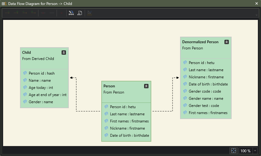
Although mostly derived classes are receiving data from non-derived classes, any class can receive data from any other. Use Data Flow Diagrams to browse the class-to-class mapping structure.
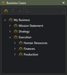
Business Cases
A Business case is a textual description of some aspect of the user’s business. Business cases use a simple hierarchical structure to organize descriptive information about specific business use cases or the business in general, with the purpose of refining the information to model form, or just keeping it as additional background information.
Any branch of the Business case hierarchy can also be generated to a Sandbox model using AI integration.
Languages

The Languages pane displays the supported target platforms, and their supported datatypes. It is more of a lookup kind of tool to check which design time attribute datatypes map onto which target platform datatypes (select datatype to view it in the Properties pane), but you can also use it as a source for ready-made transformations to apply to the data during preprocessing.
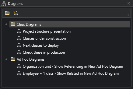
Diagrams
The Diagrams hierarchy contains custom Diagrams. Any diagrams that are under the Class Diagrams folder will be saved as part of the project, diagrams under Ad Hoc Diagrams will not.
Class Diagrams are usually constructed for some specific recurring need, while Ad Hoc diagrams are more like visual queries in nature and are created for the moment.
Power User tip: In addition to presentations, you can use Class Diagrams as a “Favorites Folder”, adding the classes you are currently working on to one diagram, if they happen not to live in the same submodel. From the diagram you can then easily apply relevant commands to all classes in one go, such as generating SQL queries or building deployment packages.
Diagram
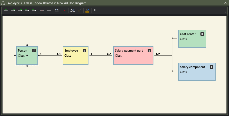
A Diagram is a free-form canvas for displaying classes and their relationships. Compared to the Model Editor, the diagram serves a different purpose: here you can freely choose which classes and associations you include in the diagram. Diagrams can be created for several different purposes, both for recurring needs and for needs you have in the moment.
You can also view a Diagram as a visual query tool that lets you browse the structure of the model. The Diagram contains functions that let you discover how classes relate to each other by visualising both incoming and outgoing references, either just to/from their closest neighbours, or recursively showing several steps of references..
The Diagram has a very different command set from Model Editor. A Diagram is not for modeling, it is for presenting, displaying and exploring.
Connections
In Connections, you can create database connections for various purposes. Typically would need to browse data (source data, DW content etc) or just have a look at the structure of the data. You can also import tables into your Conceptual model as new classes.
You can use a Connection that points to actual source data to import the table structure into DSharp Studio Modeler as classes. You can do this by dragging the desired tables from the Connections view and dropping them onto a folder or a class in the Conceptual model or Diagram.
- For each table a new class will be created.
- For each table column that is not a foreign key reference, an attribute is created in the new class (or in the class the columns were dropped on).
- For each table column that is a foreign key reference, an association is created from the new class / drop target class to the class represented by the table referenced by the foreign key, if that table is not missing from the current dragged selection. If it is, the column will be created as an attribute.
Creating a new connection defaults to a local SQL Server connection.
Note: The first database in your Database filter will be the default database of the connection, so always add at least one database to the filter!

Quick Input
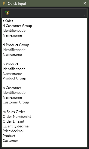
The Quick Input feature is another huge time saver that allows for one-click creation of several submodels, classes, attributes, and associations. In practice, you just need to write the desired elements into the designated text area, each on its own line. The code will then be applied to the Selected elements.
s Submodel
m/p/d/r/g New Moment – Interval / Party, Place, Thing / Description / Role / Generic Class
Attribute:Datatype
Class
Role:Class
The text in the image will yield the following content:
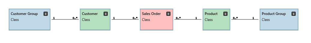
Since you still will need to write class and attribute names, this is the quickest possible way to create new content into your model.
Power User tip: In order to only have to write repeating elements once, make clever multiple selections to apply your Quick Input code to.
Description
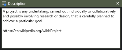
Select any element within Conceptual model or Connections and write a text describing it. The description should serve the purpose of enhancing the understandability of the model as a whole, and it should be derived from the model’s intended purpose.
For classes, the Description shows same content that is shown in the Glossary.
Power User tip: att the very least, document all classes (do that in Glossary), and also any attributes that are not immediately obvious to everybody in the workshop. Also, for any association or association end that has an optional cardinality (0..1, sometimes even 0..*), write down the cases for when there is and when there isn’t anything to be found at that end of the association.
Glossary
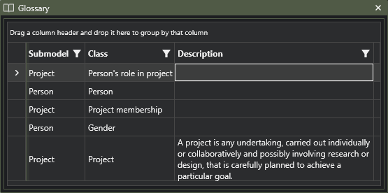
The Glossary is a listing of all Classes in the Conceptual Model. It is an excellent tool for quickly writing descriptions for all classes, one submodel at a time.
The Glossary provides extensive grouping and filtering functions.
Power User tip: spend the time needed writing down the definitions of the classes.
Power User tip: use the Glossary as a quick search function. Locate the class you’re interested in and double-click it to reveal it in the Models pane.
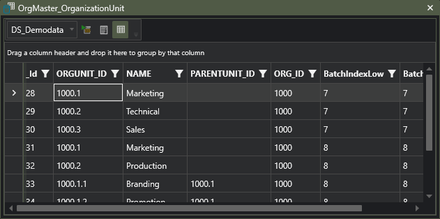
Data Grid
The Data Grid is used for browsing data. Data can be browsed for any connection defined in Connections, depending on credentials.
You can write custom SQL in the Data Grid, or, depending on your license, just click on classes or tables anywhere in the UI to display the data behind the clicked element.
Perfect for inspecting both source data and DW content.
Properties
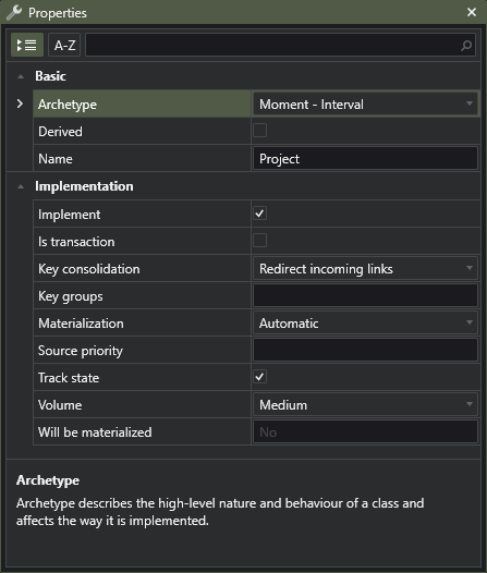
The Properties pane (or the Property Grid) is used for editing individual properties of all editable elements in the models.
Only in very few cases will the Property Grid validate and open a message box reporting an error in the property values being provided by the user. The design decision here is that it should be a quick input mechanism and not interrupt the flow. Properties affecting any implementation will be analysed in the full DSharp Studio prior to generating the implementation, so any mistakes made in the Property Grid will be caught and can be corrected at a later time.
Every element type has unique set of properties. The relevant properties are documented here.
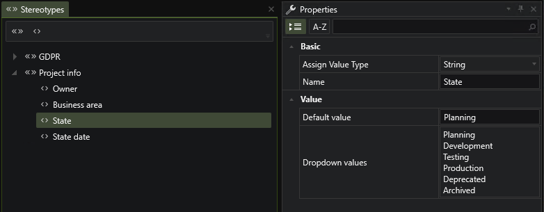
Stereotypes
Stereotypes and Tagged Value Definitions can be used to extend model elements with relevant custom information.
You can define Stereotypes with no further Tagged Value Definitions to classify model elements, ie if something has been assigned a specific Stereotype, then it represents the meaning of that Stereotype, otherwise it doesn’t. For example, a GDPR Stereotype assigned to a model element would indicate that the model element is within the scope of the GDPR regulations, and elements that have not been assigned this Stereotypes, are not.
The typical use is to use a Stereotype as a definition of a set of parameters that will be available for a model element once that Stereotype has been assigned to it. For example, you can create a Project info Stereotype that has Tagged Value Definitions for information relevant to the development of the model, like element state, owner, specific dates and so on. Once the stereotype is assigned to a model element, the user can provide values to the defined parameters.
You could also provide a Stereotype to handle element name translations: in the Stereotype, define the relevant languages as Tagged Value Definitions, assign the Stereotype to any element you need to translate, and then just add the translations as metadata to the elements.
Tagged Values
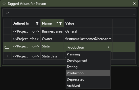
Tagged Values can be created as standalone local parameters for a model element, or they can be created by assigning a Stereotype for the element. The entire set of Tagged Values available for an element can be viewed and edited in the Tagged Values list.
Application Log
The Application Log shows messages generated by DSharp Studio. These can be general messages about executed commands, or specific error messages.

Model Analysis

Model Analysis analyzes the entire model. In addition to collecting all class related issues to one place, it will also catch minor design flaws like identically named submodels within the same parent submodel. So instead of going through your classes one by one to find issues to fix, it may in some situations be more convenient to run the Model Analysis to find all critical errors in one go. It also provides you with a good overview of the amount of unfinished modeling work.
Model Analysis requires an explicit re-analysis to update its contents.
Note that Model Analysis does not include mapping analyses. Mappings are only analyzed as part of the conversion process when changing to Run Mode.
Power User Tip: Sort the list by Severity to get the Critical errors to the top of the list
Pressing Play
Pressing Play will initiate DSharp Studio’s conversion process and the jump to Run Mode. The Analysis Engine will kick in and run an extensive analysis, this time including mappings. The Model Analysis pane will display any found issues.
- The model will need to be saved before running the model
- A full analysis will be run
- There can be no critical errors among the classes selected for building the target model
- There can be no errors in the mapping files
Note that properties mapped from some sources but not others are not listed as mapping errors, as it is quite natural that a property simply is not available from all sources. However, if a property is part of a business key, it needs to be available and mapped from all sources the class is loaded from. Also, every modeled property needs to be mapped from at least one source.
Power User Tip: you can mark unmapped properties that you still want to keep around as Derived, in which case they fall out of scope from a mapping point of view
Run Mode
Run Mode focuses on getting your solution out there, as well as keeping it fit.
In Run Mode, no design features are available. You will, however, still work with the same objects you worked with in Design Mode, classes and submodels. The main idea behind DSharp Studio is that it is much easier to work on a higher abstraction level with less details than the actual real-world implementation, and that is exactly what the Conceptual model is to the generated physical model. So even though deploying the solution means deploying tables, views and stored procedures, in DSharp Studio you can still work only with classes. DSharp Studio knows what technical implementation lies behind the classes, and transforms your class-focused UI commands to the underlying target platform’s particular brand of SQL. Couldn’t be much simpler.
Run Mode gives you a set of commands related to installing and de-installing database objects, data loading and analysis, parametrization, SQL query generation, data browsing and tools for data related problem solving.
There are also some additional panes in Run Mode.
Models (revisited)

Once Run Mode has been successfully reached, the resulting DW model will be added to the Models pane. It shows the generated database objects in a virtual Server structure.
The command set has changed from design commands to commands that initiate data loads and data object deployment.
While this is only a model, and the generated objects do not automatically install themselves anywhere, both the classes in the Conceptual model as well as the database object can be used within DSharp Studio as if they were real database objects. Open the Data Grid and click on any class or any table or view and the Data Grid will show you its data. Clicking a class shows the content of the corresponding class view, while clicking on a database object queries that object directly.
The SQL queries are sent to whichever connection is marked as being the SQL Target connection, so be sure to define your DW connection as one!
Power User Tip: Select the entire Conceptual model to load data to or install all generated classes, or select individual classes/and or submodels for loading or installing.
Class Implementation
The Class Implementation pane show all classes selected for conversion, and the objects that have been generated for them. The following content can be found here:
- Staging Area
- Each mapped source table
- Processing layer
- temporary storage work tables for each table in the Staging Area
- populating procedure for each work table
- Storage layer
- the entire set of DW storage tables for the class
- populating procedures for each table
- Model Layer
- The class view containing the most recent data from the Storage layer
Power User Tip: instead of the Models pane, use this pane to quickly access the converted classes and their database objects

ER Diagram

The ER Diagram can be used as an ad hoc diagram to quickly explore the table and view structure generated for a class. Alternatively, start with one or more tables on the diagram, and explore the database structure by individually expanding the selected table to its neighbors using either incoming or outgoing foreign key references.
Data Flow Diagram
Use the Data Flow Diagram as an ad hoc diagram to explore the data flow in and out of the generated tables. Select a table and expand to either its sources or targets, either one step or recursively.

Class Mappings

The source-specific mappings to a class are scattered around a number of mapping files, and hence not easy to find. To remedy this, the Class Mappings pane provides a quick overview of all the sources and mapping details for the selected class.
SQL Pane
The SQL pane shows the SQL code for the extended selection, where applicable.
- Classes: create statement for the class view (or materialized table)
- Tables & views: create table/view statement
- Stored procedures (generated): procedure code
- Deployment element: installation code

Deployment Pane

The Deployment pane shows the structure of the deployment package. The leaf nodes represent actual runnable SQL commands, and the Deploy command can be used to either copy the SQL onto the clipboard, or to save it into a .sql file and let the operating system run it, for example ending up in SQL Management Studio, if installed.
You can also delete unwanted branches before executing the package.